| Guideline: Feature Modeling Guideline |
 |
|
| Related Elements |
|---|
1. Introduction Feature modelling was originally proposed as part of FODA approach. Currently, it is part of feature-oriented software development approaches, which propose handling features as modular, first-class entities though the entire development cycle. In short, a feature model documents a product line’s variability. It specifies the set of valid products. Besides introducing the graphical language of feature diagrams, we also connect the graphical representation to a formal representation that is the basis of engineering tools. Feature modeling play a central role in product-line development, for example, for requirements analysis and product derivation, and are widely used in research and practice. However, no standardized modeling format has been accepted, so far. Thus, different notations and file formats are omnipresent. Additionally, research literature on feature models usually provides only small examples. Although researchers have attempted
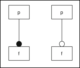
Information provided in this guideline is strongly based on Feature Oriented Software Product Lines Reference. 2. Feature Diagram Notation
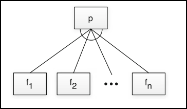
Graphical notation for a one-out-of many choice, also called alternative or mutually exclusive choice.
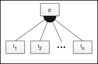
Graphical notation for a some-out-of-many choice, also called at least one or one-or-more choice.
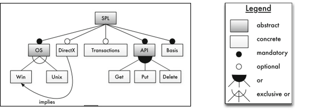
In the literature, there are many variations of feature diagrams including:
2. Some notations distinguish abstract from concrete features. Abstract features are used for structuring and documentation purposes only and are not bound to implementation artifacts. These abstract features help structuring a tree-diagram but do not reflect actual variability in the domain, as denoted below by gray boxes. It should be observe that abstract features are not mapped to any source code. 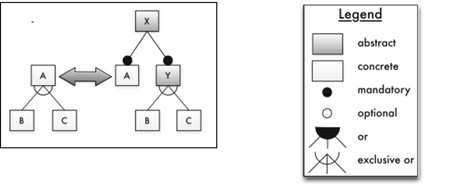 |