
Contents
1. What is VeriSensor ?
VeriSensor is a Domain Specific Modeling Language for Wireless Sensor Networks, supporting verification. VeriSensor has the features of an architectural description language adapted to a modular description of WSNs. VeriSensor offers natural modeling of a WSN to domain experts by providing high-level concepts that capture the main use cases of such systems (e.g. periodic data collection, event-detection). VeriSensor can be transformed into a discrete formal model expressed in the Instantiable Transition Systems (ITS) formalism. ITS provide a way to define a structured and hierarchical specification of a system and a notion of behavior instantiation. At this stage, VeriSensor is not intended for code generation.
2. VeriSensor Workflow
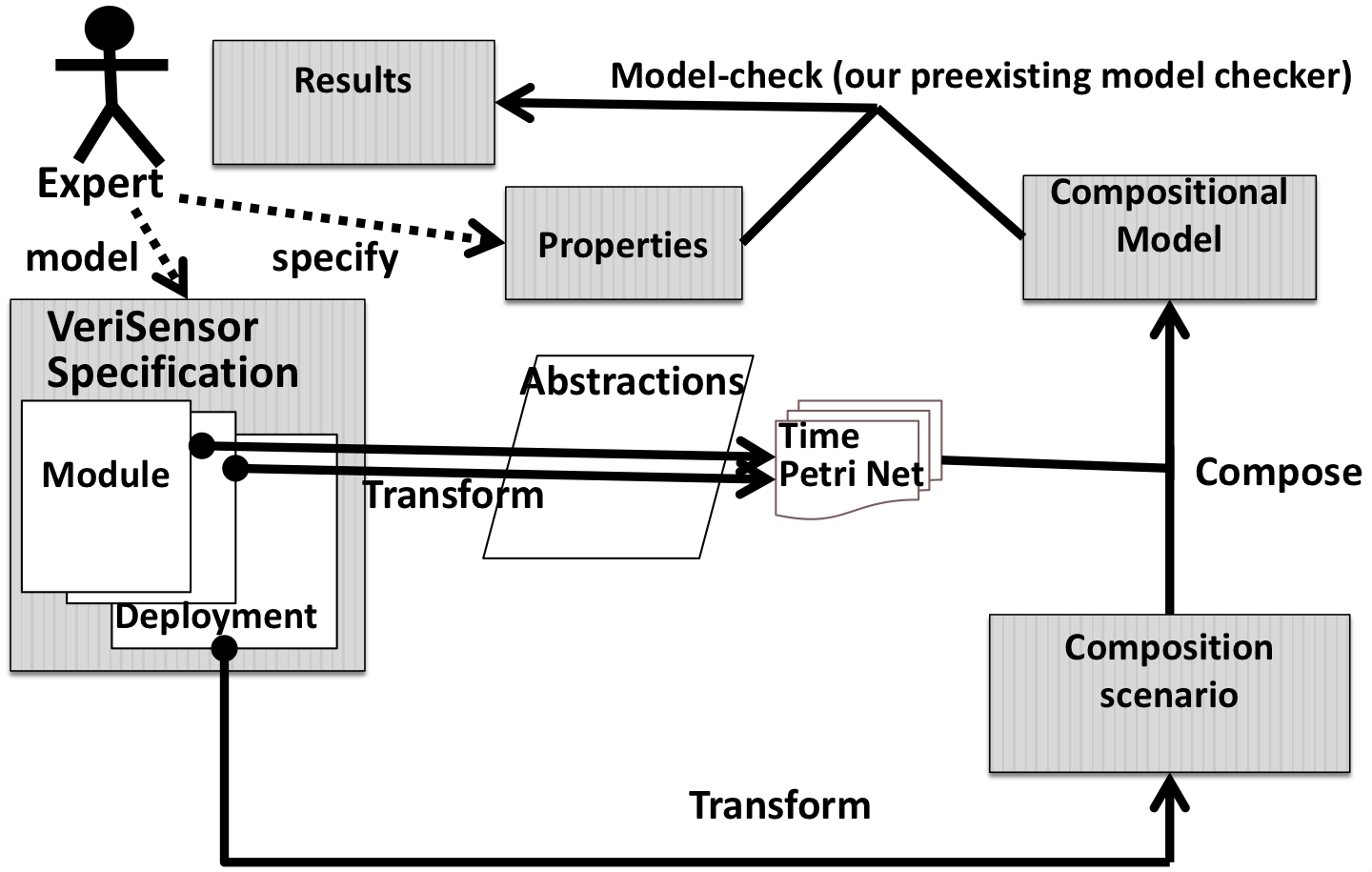
Fig. 1 presents the VeriSensor workflow.
3. Verisensor language overview
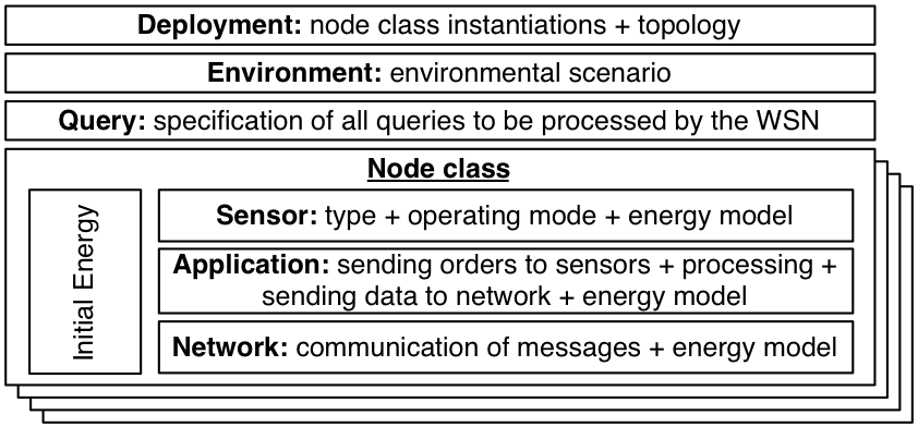
A VeriSensor specification is composed of the definition of the nodes themselves, a description of the physical environment in which the nodes evolve, the deployment of the system, and the specification of all queries to be processed by the WSN (see Fig. 2).
Description of the nodes
There can be several classes of nodes in a WSN (e.g. in a heterogeneous network), each one having its own characteristics such as:Several node classes can share common submodels and a node class can be instantiated several times when several nodes have the same characteristics.
Deployment Model
It defines how instances of node classes are spread in the physical environment and may change position over time. Engineers use this model to define the topology of the system (number of instances per class and their coordinates) as well as the logical routing of messages among the nodes.
Environment Model
It defines physical quantities as a function of space (x,y,z) and time (t). Thus, the designer may describe a particular scenario in which the WSN evolves. These scenarios are used to test qualitative properties of models on given prob- lem instances. A given environment represents a particular situation in which a given behavior of the WSN is expected.
Query Model
It describes the queries to broadcast and process in the WSN. Queries ask to periodically sample physical quantities for a certain duration. A periodic query requires the node to regularly send sampled data to the base station. A conditional query only signals the base station when the condition is met. This allows to model both periodic data collection with a periodic query of an infinite duration, and event detection , using a conditional query that characterizes the event.
Structuration in VeriSensor
The various submodels are defined separately in VeriSensor to support modularity and reusability of WSNs components. The deployment model of a system is the entry point of a VeriSensor model. It references the Environment model and instantiates all nodes from the definition of their classes.4. Verisensor syntax examples
4.1. Example 1
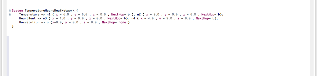
Fig. 3 shows the deployment parameters of a medical sensor network, monitoring many patients in a hospital room. We consider here a static routing scheme. Each node instance is parameterized by its position and next hop. For instance, the node n1 of class Temperature is located at position (6.0,6.0,0.0) and routes messages to the b instance. Distances are expressed in meters. The editor supports syntax highlighting (bold and colored keywords).
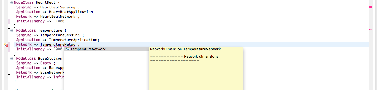
Node classes (see Fig. 4) specifies the physical characteristics of a node. It relates the data dispatched in the following aspects: sensing, application, network, and the initial energy.
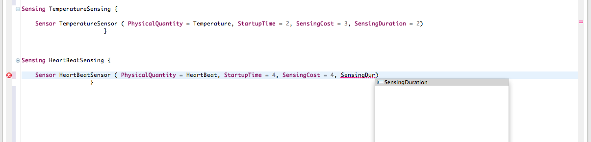
Sensors (see Fig. 5) are described through their main technical characteristics: the measured physical quantity, the startup time (i.e. the time for the sensor to be operational after being turned on), the sensing duration (i.e. the time for the sensor to sense the value), and the energy cost of collecting a sample. For instance, HeartBeat measures the heartbeat and starts-up in 2 time units and consumes 3 energy units. The editor supports syntax error detection and content completion (an error is signaled and the sensingDuration keyword is proposed).
--> Full model file (TempHeartBeat.verisensor)
--> Data files referenced in the model file (the fields for each line are : (x,y,z,duration,physical quantity value)):
FluctuatinTemperature.data
IncreasingHeartBeat.data
IncreasingTemperature.data
ConstantHeartBeat.data
4.2. Example 2
Modeling HipGuard, a sensor network for monitoring the hip angle and the load on the foot, after a hip surgery( see : original paper )
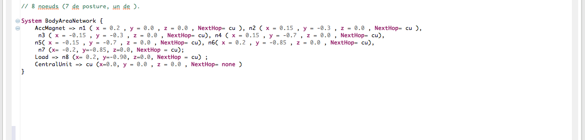
Fig. 3 shows the deployment parameters of a the hip guard sensor network, monitoring a patients recovering from surgery. The network contains one node measuring the load put on the foot (n8), and 7 nodes measuring the triple-axis acceleration and magnetic field (n1 to n7). Distances are expressed in meters. The editor supports syntax highlighting (bold and colored keywords).
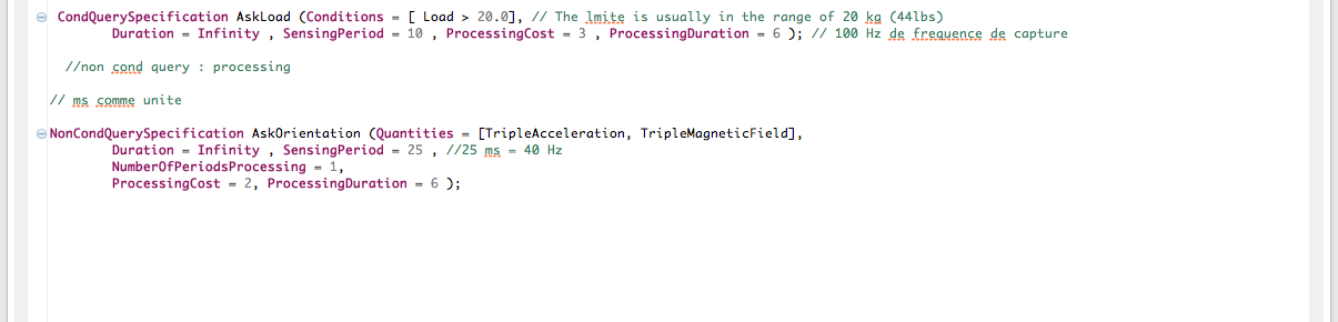
The queries model specifies the list of queries processed by the sensor network. There are two types of queries : conditional and non conditional. A query senses periodically physical quantities during a certain duration. Every sample is processed and sent to the base station. A conditional query sends data to the base station (b) only when the condition is verified.
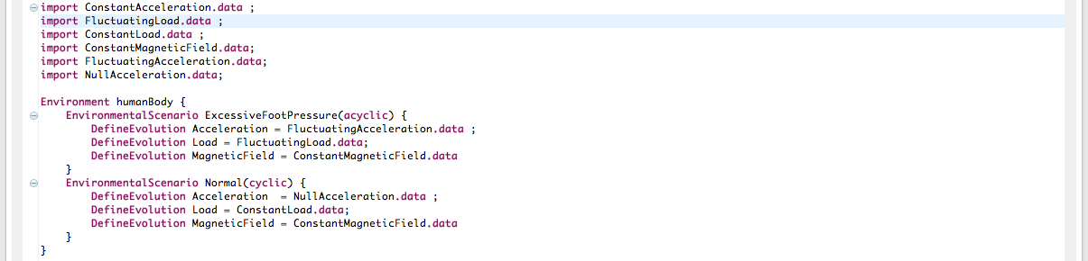
The environment model specifies a list of environmental scenarios. An environmental scenarios assigns to every physical quantity a .data file name specifying the evolution of the quantity.
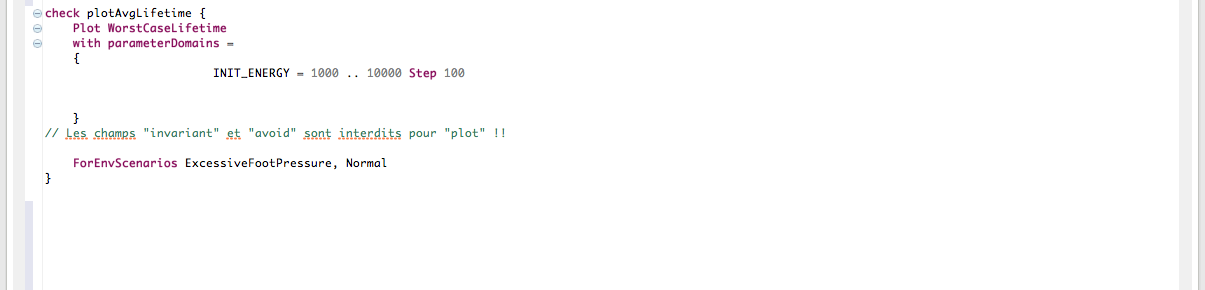
The modeler specifies what he wants to do with his model. He has 4 possible actions : plot a metric, maximize a metric, minimize a metric, verify a property. In this case, the modeler specifies to plot the worst case lifetime of the network as a function of the initial energy of the nodes, for the environmental scenarios : excessiveFootPressure and Normal.
--> Full model file (plotHipGuard.verisensor)
--> Data files :
ConstantLoad.data
ConstantTripleAcceleration.data
ConstantTripleMagneticField.data
FluctuatingLoad.data
FluctuatingTripletAcceleration.data
NullTripleAcceleration.data
5. Implementation
The prototype tool (still a beta version) is implemented in Java. It offers an Xtext based front-end in Eclipse (with syntax coloration, context assist, etc.). A transformation engine based on the VeriSensor metamodel builds the ITS representation.
If you want to access the work around VeriSensor, you are welcome to browse the svn and have a look at the source code:
https://srcdev.lip6.fr/trac/research/ybenmaissa/browser/Mapping-Verisensor-To-ITS
The development release of Verisensor can be checked out with the following command:
svn co https://srcdev.lip6.fr/svn/research/ybenmaissa/Mapping-Verisensor-To-ITS
(this is an eclipse plugin : eclipse development environment and Xtext required)
The download version will be available soon :-)
6. Useful links